Switching buttons in electronic devices using electronic swtiches and microcontrollers
Many electronic devices have buttons that are used to control them. Such buttons are intended to be operated by humans. They can't be pressed digitally
, but we can hack them so that a microcontroller or GPIO from a mini computer can press them
using electronic switches.
In this article I'll show how to modify a key chain camera so that a PyMCU microcontroller can turn the camera on and take pictures, record video clips.
The camera used for the experiment
I wanted to use something handy for the experiment, yet cheap so that it won't be a problem if it breaks. So I've went to local gadget shops and found a very cheap key chain camera - microSD for storage, mini USB for charging and transferring files. It has two buttons. One needs to be pressed by more than one second to turn the camera on. The second one if pressed short will make a photo, if longer - will start a recording. I needs to be pressed to stop the recording too.


I unscrewed two screws and I could take the camera module out. On the PCB there are two buttons that I'll modify


The quality of images and videos made by this cheap camera is very very low - but it works, and is cheap.

There are four connectors on every button so I had to check which pins are the ones that need to be connected. I used a jumper wire to connect button pins and observed which pair would trigger camera action. It turned out that the left side of button pins have to be connected. So I've soldered wires to those pins. Later on those wires will be connected to an electronic switch.

Electronic switches
For low currents transistors can be used as switches. GPIO for the base, and the two wires that would be switched on/off to the transistor emitter/collector, but depending on your transistor type you have to connect those wires (polarity +/-) to the correct pin of the transistor.
Aside of transistors there are other switches, like relays. I used a solid state relay LAA110. It's a low power switch that will close a circuit when it gets current on the control pins (like: digital pin at hight state and GND)

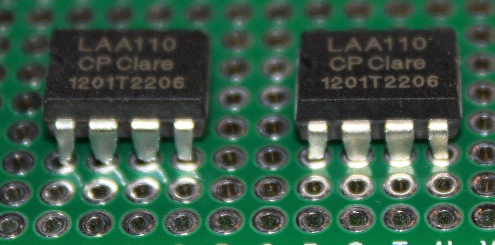
One LAA110 chip has two switches so it will handle the camera. As it's small I had to use a universal PCB. When I soldered it I did a test with a LED circuit. When the GPIO pin connected to the control pins of LAA110 was in high state the LED shined - so everything works. The good thing about this switch is that it doesn't has any polarity requirements on the wires it connects, and that it optoisolates control circuit from those wires.

Some devices may use higher voltage, current on their circuits - like those powered via power adapter. It's a good thing to check that before using an electronic switch as that switch must be able to handle that current.
Pressing electronic switch from a microcontroller

I've soldered the camera wires to the relay switchable pins. The control pins were connected to D1 and D2 digital pins and GND. D1 was for the power button, D2 for the recording, picture taking. So having that I wrote some code to operate the camera from pyMCU:
from time import sleep

import pymcu


class Camera(object):
    START_BUTTON = 1
    REC_BUTTON = 2

    def __init__(self, mb):
        self.mb = mb

    def toggle_camera(self):
        self.mb.pinHigh(self.START_BUTTON)
        sleep(3)
        self.mb.pinLow(self.START_BUTTON)
        sleep(2)

    def take_picture(self):
        self.mb.pinHigh(self.REC_BUTTON)
        sleep(0.5)
        self.mb.pinLow(self.REC_BUTTON)

    def toggle_recording(self):
        self.mb.pinHigh(self.REC_BUTTON)
        sleep(4)
        self.mb.pinLow(self.REC_BUTTON)


mb = pymcu.mcuModule()
camera = Camera(mb)
camera.toggle_camera()
camera.take_picture()
#camera.toggle_recording()
#sleep(5)
#camera.toggle_recording()
camera.toggle_camera()
The class switches pin states and waits needed amount of time for it to take effect on the camera. Plain camera became now controllable by other electronics. Just by simply hacking
buttons it had. There are many devices that can be modified this way, so it's up to your imagination about what to digitalise
.
A non-invasive way would be to use a servo that would physically press the button, but that requires servos and also they have to be properly mounted which may not be that easy.


Comment article